


0-10V Wiring: It’s Not as Difficult as You Think!
Let us continue to learn about 0-10V from where we left last time. We discussed about 0-10V basics, if you haven’t read that, you can read it here Basics of 0-10V and some interesting facts.
Since wiring is an important element in any lighting network, in this blog we will discuss about 0-10V wiring. Like a human brain, control wiring communicates, commands and passes information between control devices in a lighting network. If the wiring is not proper, it will lead to severe problems.
So now let us discuss about 0-10V wiring in detail. Shall we?
You might be aware that the classification of various wiring systems is detailed in Article 725 of National Electrical Code (NEC). And, when considering the 0-10V dimming, NEC classifies the wire systems as Class 1 and Class II.
| NEC is the benchmark for safe electrical design, installation, and inspection to protect people and property from electrical hazards. |
Class 1 wiring refers to line voltage conductors that transmit current at a value of up to 600 volts. It requires wires with insulation rating for the voltage carried (usual wiring has 600V rated insulation), or conduit, or a protective cable assembly. Class 2 wiring is defined as low voltage conductors with low current and do not have enough voltage or current to pose a hazard and have less stringent installation standards in terms of wiring protection. The best thing about Class 2 wiring is that it can be installed free within the wall or ceiling without protection of conduit or a cable assembly, otherwise line voltage rated insulation.
Class I vs Class II wiring
| Class I- Line Voltage Wiring | Class II- Low Voltage Wiring |
| Typically 120V or 277V AC | Typically 10–24V DC |
| Provides both power to lighting fixtures and also a means of grouping them by circuit/switch-leg within “control zones” | Provides a pathway for communication of analog or digital signals, such as incoming sensor input data—e.g., light levels, occupancy conditions—and outgoing commands. |
| It is not very flexible, imposing limited control options and rigid zoning based on lighting circuiting | Is inherently flexible as most codes do not require it to be installed in conduit. |
The Common types of cables used in low-voltage wiring include:
- Unshielded Twisted Pair (UTP) cable
- Fiber optic cable — used for long-distance
- Speaker wire
- Thermostat wire
- Coaxial cable (coax)
- Security system wire
Now let us see the Class 1 wiring methods recommended in NEC Requirement 725.48
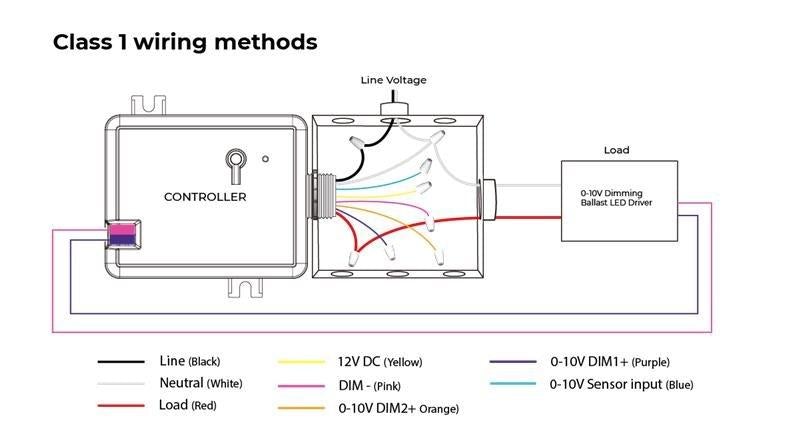
Class 1 circuits are allowed to install with other circuits as specified in 725.48 (A) and (B):
(A)Class 1 circuits may share the same cable, cable tray, enclosure, or raceway, regardless of whether they are alternating or direct current.
As long as all conductors are insulated to the maximum voltage of any conductors in the cable, cable tray, enclosure, or raceway.
(B)Class 1 circuits may be established using power supply wires that meet the following requirements:
(1) Class 1 and power supply circuits shall be allowed to occupy the same cable, enclosure, or raceway only when associated functionally.
Did you know????
The 0-10V driver and ballast are labeled “Class 2” because the ballast is a sink of power not a source. When the ballast is the sink of a Class 2 limited power circuit, the circuit shall be identified as “Class 2 Circuit” to indicate that the ballast is intended for connection to a Class 2 circuit.
As we have completed the wiring requirements of Class 1 circuits, let us look into the factors that matter in Class 2 wiring!
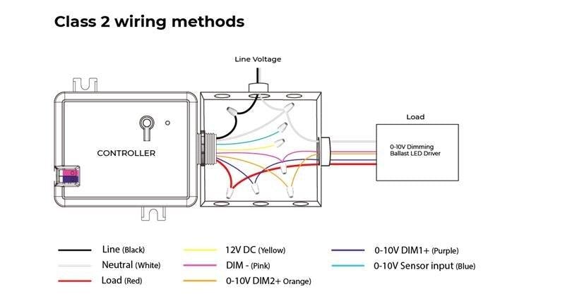
Class 2 circuit conductors in enclosures, compartments, outlet boxes, device boxes, or similar fittings shall be permitted to be installed with electric light, power, Class1,…circuits where they are introduced solely to connect the equipment connected to Class 2 circuits and where (1) or (2) applies:
(1) Class 1 circuit conductors are routed to maintain a minimum of 6 mm (.25 in) distance from the conductors and cables of Class 2.
(2) The circuit conductors operate at 150 volts or less to ground and also comply with one of the following:
- The Class 2 circuits are installed using Type CL3, CL3R, or CL3P or permitted substitute cables provided these Class 3 cable conductors extending beyond the jacket are separated by a minimum of 6 mm (0.25 in) or by a nonconductive sleeve or nonconductive barrier from all other conductors.
- The Class 2 circuit conductors are installed as a Class 1 circuit
0-10V ballasts and drivers have a minimum spacing of 0.25 inches between line voltage and the bus terminals for Class 2 installations
Things to Remember!
| All the device (controllers & drivers) should mark whether they are 0-10V class-1 or class-2. Based on the local codes, If a class-2 device is wired along with a class-1 device, the class-2 device need to do reclassification. The requirements for the reclassification include; Larger wire gauges Insulation requirements (Installation as Class 1 requires 600volt insulation on dimming conductors sharing a conduit with line voltage conductors) Adding class-1 labels over the class-2 markings |
Is the connection of the wires important in 0-10V wiring?
Yes!
0-10V topology is an analog technology based on the voltage difference between two wires. This voltage difference results in the polarity sensitivity of low-voltage control wires. So, you have to make sure that the wiring connection is done properly. If the wires are switched, i.e., if not connected in the right way, the entire 0-10V, the drivers and ballasts will not function efficiently.
For example: Wire 1 must be connected to connection 1 on every device and wire 2 connected to connection 2.
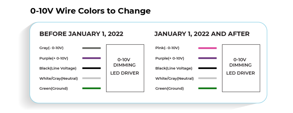
0-10V Wire Colors to Change
When it comes to 0-10V wires, there is something exciting stored for 2022! As you know the 0-10V wires were purple and gray for a long time. To avoid the confusion with gray 277 V~ neutral wires, the NEC prohibits field-connected control wires from being gray. It will be pink with effective from January 1 2022 .
What is the recommended 0-10V gauge wire?
The most commonly used wiring is stranded-copper twisted-pair because stranded copper provides a more stable current path. Even though the typical sizes range from 14AWG to 22 AWG, the most widely recommended size is 18 AWG. The wiring size can be increased if voltage drop is a concern.
How far can I run a low-voltage 0-10 V circuit?
It depends on the number of ballasts /drivers, source rating of each ballast/driver and the gauge of the wire.
Points to remember
- Mixing Class 1 and Class 2 wiring in the same conduit is not permitted.
- Ran separately or at least separated by a continuous barrier.
- Running 0-10V dimming wires in the same conduit as Class I wiring is allowed if the devices are rated for Class 1 wiring, and the insulation requirements are met.
We hope you find this blog helpful. Please feel free to connect with us to discuss your comments and thoughts. In the next blog you can read on 0-10V dimming curves.
Please comment your thoughts and feel free to contact us!